English
 中文
 Русский
Nov 09, 2026

A buyer specifies a 12-way distribution box for a small commercial fit-out. The circuit schedule lists ten outgoing ways. It looks like a comfortable fit with two spare. The enclosure arrives, the electrician mounts the DIN rail, fits the main switch and surge protection device, and then stops: after those two components alone, only eight module positions remain. Two circuits from the schedule now have nowhere to go. The box is not defective. The specification was.
This is the most common capacity error in distribution box circuit capacity planning: treating the number on the label as the number of circuits available in the field. This guide explains why that gap exists, how to calculate the usable capacity you actually need, and which specification decisions determine whether an enclosure has room for the installation as designed — not just as advertised.
The confusion starts with vocabulary. A way on a distribution board is a supplier-defined position, not a universal unit of circuit capacity. A module is a physical width on the DIN rail. Under DIN 43880, the standard modular width is 18 mm, and most single-pole MCBs occupy one module. A pole describes how many conductors a device switches or protects. A circuit is an outgoing electrical path.
These dimensions do not map one-to-one. A single-pole MCB may use one module and serve one circuit. A double-pole RCBO may use two modules and still serve one circuit. A three-pole device uses three modules and serves one three-phase circuit. The same “way count” on two different products can therefore translate into very different usable configurations.
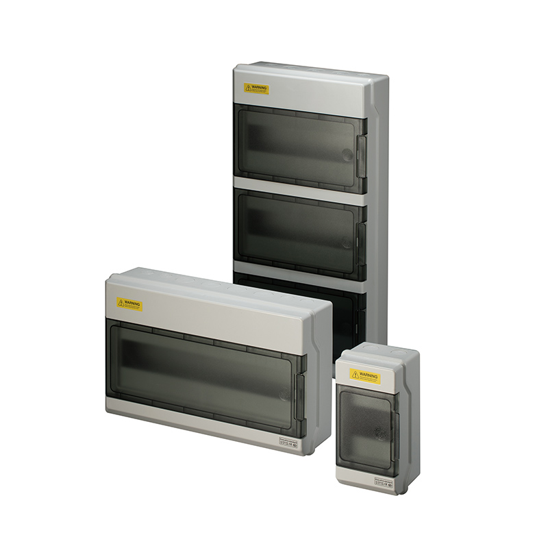
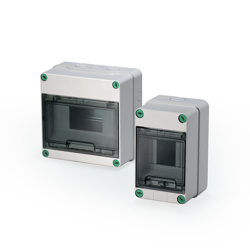
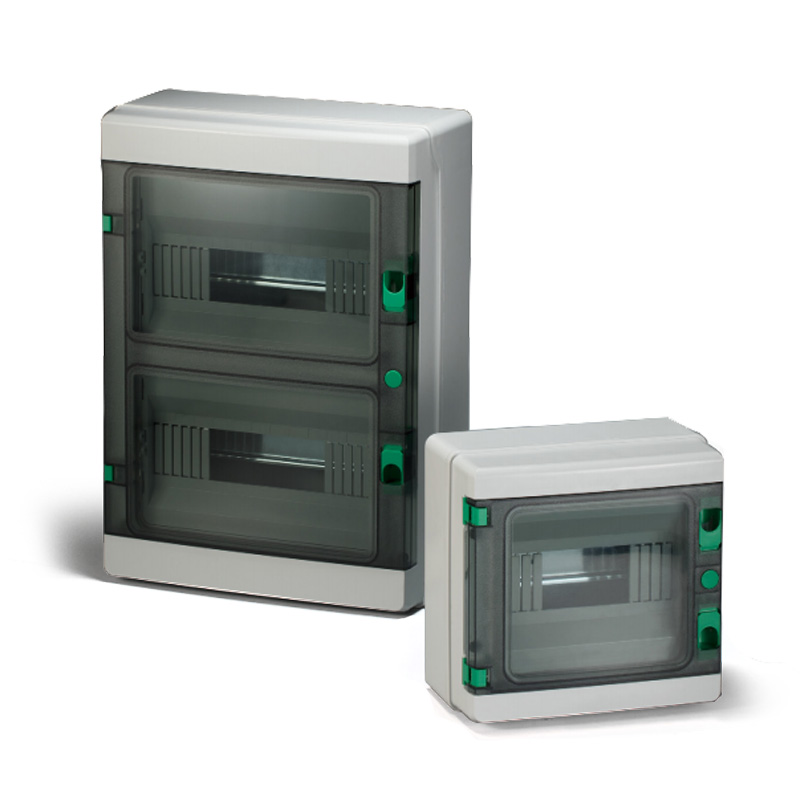
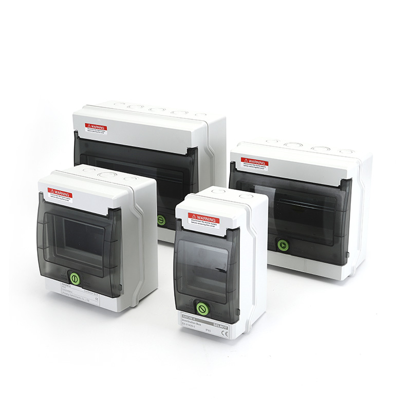
The practical consequence is that distribution box circuit capacity should never be confirmed from the headline way count alone. It should be confirmed from the device schedule and the manufacturer's definition of usable module space. SELHOT's modular range illustrates the range a buyer is working within: the SHPN series spans 4 to 36 modules in a single product family, which means the difference between a marginal specification and a comfortable one may sit within the same series rather than requiring a different product line. Reviewing how a modular range is structured — for example, the way-count and terminal-current envelope of the SHPN modular distribution series — is a more reliable starting point than picking a single number and hoping it fits.

Every device mounted on the DIN rail competes for the same module width. The outgoing MCBs are only one group of occupants.
| Device group | Typical module footprint | Notes |
|---|---|---|
| Main switch / incomer | 2 modules | A 100A double-pole main switch commonly consumes two 18 mm spaces |
| Surge protection device (SPD) | 2 modules | Pre-wired Type 2 SPDs are often factory-allocated two spaces |
| RCD / RCCB | 2–4 modules | Double-pole and four-pole devices consume proportionally more width |
| RCBO | 2 modules (typical) | Combines overcurrent and residual current protection in one device |
| Metering / control accessories | Variable | May be separate from outgoing capacity or share modular space |
| Neutral and earth terminals | Separate from module count | Still require physical depth and cable-bending room |
A widely cited installer example makes the arithmetic concrete: a 12-module board fitted with a 100A main switch (2 modules) and a pre-wired Type 2 SPD (2 modules) leaves 8 usable outgoing ways, not 12. An 18-module board under the same configuration leaves 14. The label did not lie; it counted modules, not circuits.
This is why distribution box circuit capacity has to be calculated from a device schedule rather than estimated from a product name. The calculation follows a simple order: start with the required outgoing circuits, add the module width of every fixed device, add any specified spare ways, and compare the total against the enclosure's usable module width — not its nominal way count. A supplier that publishes usable module capacity per row, rather than only a headline way count, gives the buyer a number that can actually be checked against the schedule.
For enclosures where the internal layout is fixed rather than fully modular, the same principle applies in a different form: the enclosure must accommodate the cable entry, terminal arrangement and bending radius of the devices specified, not just their face width. A box can pass the module-count test and still fail the installation because the depth is insufficient for a 63A device with a 90° cable bend.
Reserve capacity is often specified as a percentage — “add 20% spare” — but the more useful question is which future loads are foreseeable and what module footprint they will require.
A spare way that cannot accept the device you later need is not spare capacity. An EV charger circuit may require a dedicated RCBO and a larger cable; a small “spare” position at the end of a rail may not have the depth or gland access to accommodate it. A PV combiner expansion may require additional string fusing and surge protection, consuming multiple modules at once. Reserve should be planned against the device list, not against an abstract percentage.
The cost asymmetry matters here. Moving from a 12-module to an 18-module enclosure is typically a small increment at the point of order. Returning to a site to replace an undersized enclosure — with the labour, downtime and re-certification that entails — is a different order of cost. This is the practical argument for calculating capacity from the circuit schedule with named future loads, rather than sizing to the current count and assuming spare ways will absorb whatever comes next.
Beyond device footprint, four factors determine whether a distribution box will deliver the capacity its label suggests.
Enclosure depth and cable space. Module width is a two-dimensional measure. Depth determines whether devices can be mounted, wired and closed without compressing conductors. A shallow enclosure with a high way count may be unusable for anything beyond single-pole MCBs with small cable.
Rail configuration and usable width per row. A multi-row enclosure distributes modules across rails. The usable width per row may be reduced by end barriers, terminal blocks or the position of the cable-entry plate. Buyers should ask for usable modules per row, not just total modules.
Knockout and gland-plate design. Cable entry consumes physical space that may not appear in the module count. Removable gland plates and pre-formed knockouts affect how much of the enclosure's internal volume remains available for wiring. For projects where the cable schedule is finalised late, a removable-knockout design offers more flexibility than a fixed plate.
Application-specific device requirements. DC applications, EV charging circuits and three-phase distribution each impose device types that consume capacity differently. A PV combiner may need string fusing, a DC isolator and an SPD in the same enclosure — a combination that a standard AC way count does not anticipate.
These factors converge on a single procurement habit: request a dimensional drawing and a usable-module statement before releasing a purchase order. A front-view photograph and a way count are not a capacity specification.
Consider a mixed-use commercial unit with ten outgoing lighting and power circuits, a planned EV charger, and a rooftop PV connection. The circuit schedule lists ten current circuits, one future EV circuit, and one future PV-associated circuit.
A naive approach specifies a 12-way box for the ten current circuits and treats the two future circuits as “spare”. A capacity-based approach counts differently:
Ten outgoing MCBs: 10 modules
Main switch: 2 modules
SPD for the incoming supply: 2 modules
One RCBO reserved for the EV circuit: 2 modules
One way reserved for the PV-associated circuit, with allowance for a device width consistent with the PV design: 2 modules
The total module requirement is 18 before any additional spare. An 18-module enclosure is the minimum that fits the planned configuration; a 24-module enclosure provides genuine reserve. The “12-way” enclosure was never a candidate once the device schedule was laid out.
This is the scenario where the broader IP65 distribution box selection framework becomes relevant: capacity is one selection axis, and it interacts with material choice, IP rating and mounting. A box that has the right module count but the wrong enclosure material for its location is still a specification error, just a different one.
The same logic scales across project types. A construction site board may need impact-resistant housings and flexible connection points; a PV combiner may prioritise DC protection and weather sealing; a marine installation may require anti-corrosion contacts and a higher IP rating. Each application shifts which devices occupy the rail and which enclosure properties matter most. Buyers can review how industry-specific enclosure configurations change the capacity and protection requirements across construction, renewable energy, industrial automation, mining and marine environments — a useful cross-check that the capacity figure calculated for one project is not simply carried over to another with different environmental and device constraints.

Once the usable module requirement is known, the shortlist follows from the range that covers it. A requirement of 18 usable modules after fixed devices will not be met by a product family whose maximum is 18 total modules; it requires a family that publishes usable capacity at or above the calculated figure.
SELHOT's SHA series spans 4 to 36 channels with a 75A terminal rating, which means the same product family can accommodate a small sub-board and a larger distribution application without changing enclosure architecture. The SHPN series offers the same 4–36 way envelope with IP66 protection for locations that need jet-wash resistance. For buyers whose capacity requirement is modest and whose environment is sheltered, the SHT series provides 4–12 channel configurations with a removable knockout design, which is a different capacity and installation trade-off rather than a smaller version of the same specification.
The product selection step is not “which box has the most ways”. It is “which enclosure publishes a usable module capacity that matches the calculated requirement, in a material and IP rating appropriate to the location”. For projects that combine distribution boards with junction boxes, isolators or industrial connectors, the same capacity discipline applies to each enclosure in the system — the junction box range and isolator range are specified on terminal capacity and device footprint, not headline counts.
Capacity planning is the first filter. Once the required usable module width and the environmental constraints are both confirmed, comparing series specifications is a short exercise rather than a search through catalogues.
IP65 Distribution Box Selection: Beyond Water and Dust Protection
DIN Rail Layout, Enclosure Size and Installation Space: A Buyer’s Guide
This article is part of SELHOT’s technical content library. No direct sales or pricing information is included. All technical discussions aim to help you make informed purchasing decisions.